I’ve been on the move for the last 25 years or so – following the great opportunities I’ve been given as a roving wireline engineer (fancy name: operational petrophysicist). The hardest places to work are always the most rewarding, and as they say the sign of a true adventure is it’s not very funny at the time (I’ve had quite a few of those but I’m always ready for more).
Naturally I carry a camera on my travels (and I need one for my job). Although digital is by far the most sensible & practical option (for the sheer capacity to collect HQ images) it generally leaves me unsatisfied on a personal level – there is nothing gratifying about the process and let’s face it: we all need a little bit of magic to keep going…
The Problem
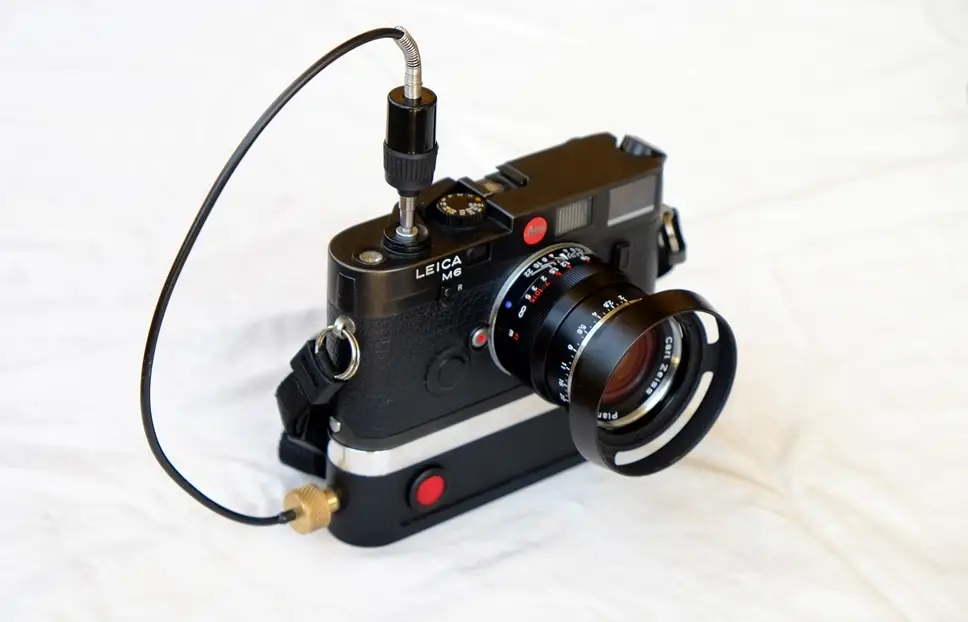
Whenever possible, I take along a film camera, either Olympus mju-ii, or OM4Ti, or Leica M6. If taking a break it’s always the M6: around my neck or on the table (breakfast to bedside). I found myself (quite often) wanting to take group photos with family or colleagues but I had no means of achieving that with the M6. I thought about a mechanical timer but I wanted a device that could do a bit more. Since I could not buy what I needed I decided to make one. The design criteria were set as below:
- A unit which could stay attached to the camera
- A unit that would not be excessively large or heavy
- A quick plug-in actuator for group shots when needed
- A simple remote control with reasonable range
- A better anchor point for the tripod (Leica’s cantilever connection creates a tuning fork)
- A leveling sensor to keep the ‘horizon’ straight
- Programmable & flexible (long exposure, timed release, for example).
So the project was born and I started pottering away last November, doing my homework on what might be possible. It’s been a nice distraction from work, and I learned a lot in the process. Thanks to youtube as a fantastic resource – with a bit of effort you can find real enthusiasts for just about anything.
Working the Solution
I started off by accurately measuring the M6 base-plate. It is quite a complex form to reverse engineer since you have a radial profile at the front and an elliptical one on the back. Furthermore, I needed to positively align the unit with the M6 body by creating a precise radial lip that would sit inside the front half of the base-plate screw recess.
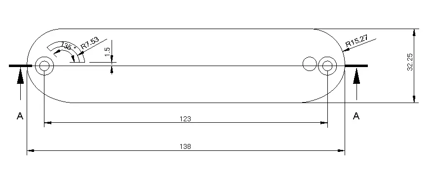
Once I had established the overall unit dimensions (which could not change as per point #2 of the criteria) I had to evaluate the different actuation and control options.
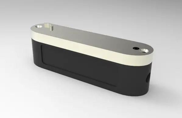
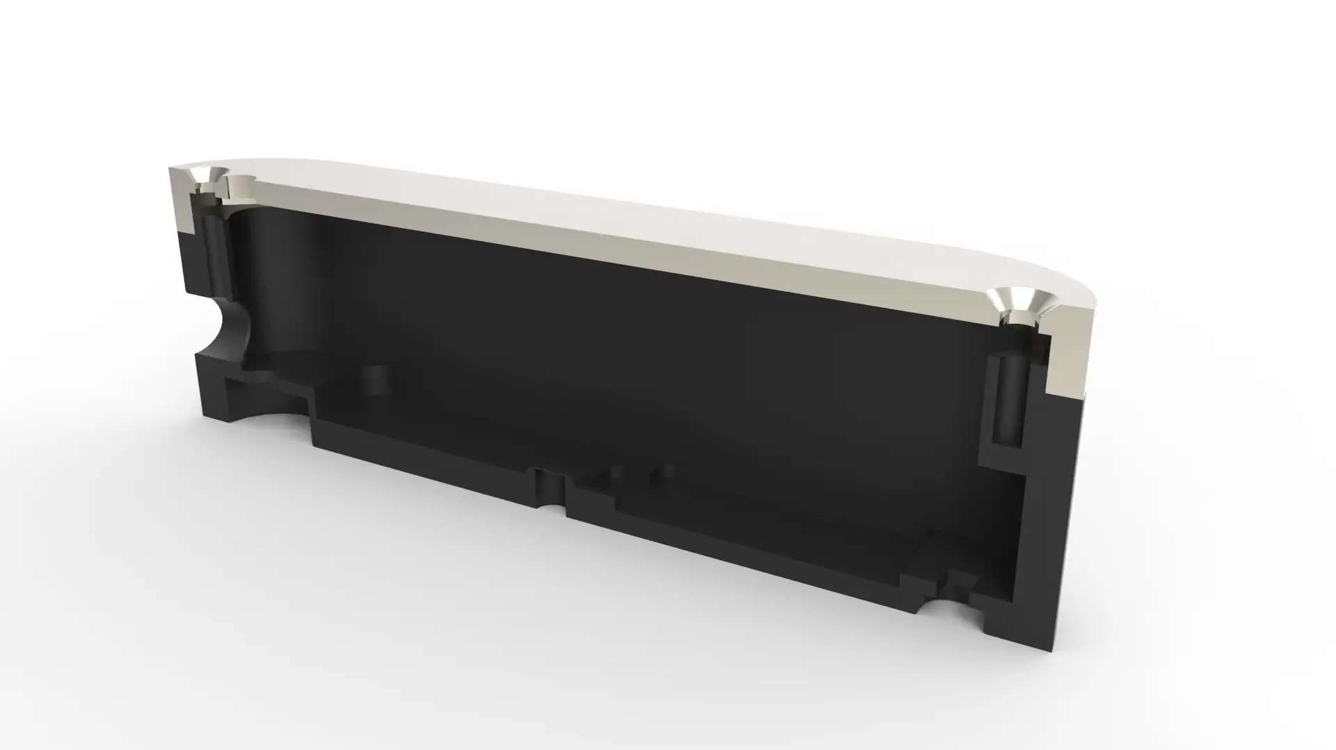
Actuation
For actuation I chose air for a few reasons:
- Air shutter releases are already proven
- Air is a natural damper
- There are plenty of second hand “screw in” actuator units available on ebay
- If you spring a leak nothing bad will happen (I tested the stroke force with my defunct OM1)
- The hose (or mechanical trigger) has to exit the right hand side of the unit (otherwise you are scratching you are left ear with your right hand going over the top of your head). The mounting bolt blocks the path for a mechanical actuator, whereas “plumbing” can go around the bolt and exit the unit in the logical place (as it should)
Communication
For communications I chose infra-red for a few reasons:
- It’s a conventional system for camera shutter actuation
- I had an old IR remote from a Nikon D40 (which is long gone)
- Mobile phone integration was possible (Bluetooth) but I saw that as an un-necessary complication
Control, Levelling, Piston Drive & Power
For control I chose an Arduino Nano due to its small size, ease of use, and great support networks (low cost too – from £1.50-£4.00 depending on where you shop).
For the levelling sensor I used an ADXL-335 which is fixed to the base of the unit – I included an offset pot for fine tuning (as you do)
For piston drive I chose a Firgelli actuator with position feedback to allow control of peak pressure. The pneumatic piston was custom made with low friction piston to reduce current draw.
For power I used what was available (AAA batteries). Better to have rechargeable but I have limited choices in my current location – I had to improvise with what I had (pretty much like my job).
Assembly
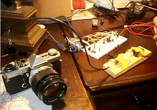
Once I had the components assembled (which took a very long time) I made a breadboard and wrote the code, testing each part separately: as below with OM1 (note use of medical syringe to generate pressure) – this is a screenshot from a video – hence poor quality. The piston diameter was limited by the inside dimensions and need for 4 x AAA batteries, which eat up a lot of space.
The starting point for the unit body was a 3 ¼” billet of Aluminium. I had no choice in the grade, again I just used what was available.
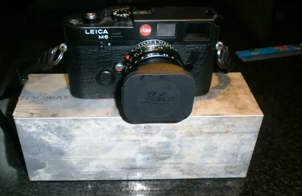
The completed Project
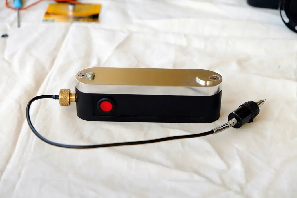
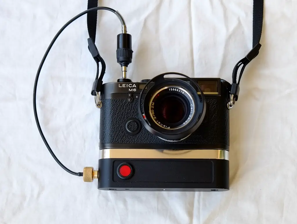
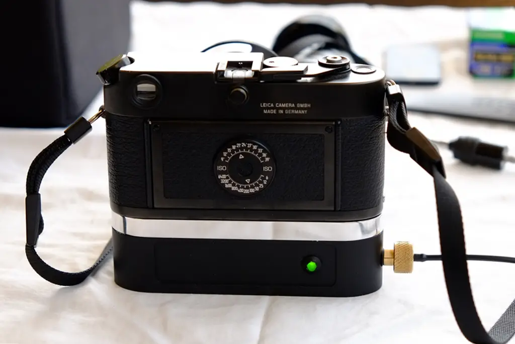
The unit could be mass produced but I have no commercial aims (and no time). I’m not the right guy to do that anyway – there is a very large step between prototyping (my prime domain) and making a consumer product. Lost wax casting would be the way to go for the body (CNC machining is too expensive) and a custom board with SMD components would be needed, with rechargeable batteries. I imagine the interest and market would be pretty small anyway.
It took a while (and patience) to get everything to fit nicely and work as intended. Looking forward to taking it on a trip somewhere – I now have to get used to the idea I can be in the shot too!
Share this post:



Comments
Terry B on DIY Leica M6 remote shutter release – Guest post by Guy
Comment posted: 03/08/2016
Sean Fisher on DIY Leica M6 remote shutter release – Guest post by Guy
Comment posted: 03/08/2016
Can you give me an email?
[email protected]
Kyle Ting on DIY Leica M6 remote shutter release – Guest post by Guy
Comment posted: 03/08/2016
Comment posted: 03/08/2016
Ray on DIY Leica M6 remote shutter release – Guest post by Guy
Comment posted: 03/08/2016
Eddy on DIY Leica M6 remote shutter release – Guest post by Guy
Comment posted: 03/08/2016
Alex Hakimi on DIY Leica M6 remote shutter release – Guest post by Guy
Comment posted: 03/08/2016
jeremy north on DIY Leica M6 remote shutter release – Guest post by Guy
Comment posted: 04/08/2016