If you have read some of my posts here, you know that I am a newbie where it comes to film photography. This time I thought I would share something about optics, a subject that I do have some experience with. During office hours I am an engineer in opto-mechatronics, an area where mechanics, electronics and optics are combined. One of the most familiar mechatronics system is a CD player, and in the past I have worked at Philips Research on similar systems in the Optical Storage department (CD/DVD/BluRay). It is mainly in this group where I heard the nice story that I want to start with, as it helped me gain some insight in the very basic behaviour of light. I thought I’d share this here as it may be interesting to other photographers too. I will try to explain some basic principles without the use of equations 🙂 .
Imagine you are a lifeguard, and some swimmer has gotten into problems and is calling for help. Suppose you are at the blue spot in the diagram below, and the swimmer is located at the red cross. What would you do to get to the swimmer as fast as possible? You might choose to go in a straight line towards the swimmer (route 1 in the diagram below), as this is the route with the shortest distance. But this route will require quite a bit of swimming, which will be slower than running in the sand, even if you are a trained lifeguard. Option 2, where you run in parallel to the shore until you are at the same height as the swimmer will lead to the lowest amount of swimming, but will result in a longer trajectory. If you calculate the fastest path you will find that it is somewhere in between, or route 2. The exact angle that the path on sand and in the see make depends on the two velocities. However, it turns out that light works like this, it chooses the fastest path from one point to another, taking into account the different velocities it will encounter.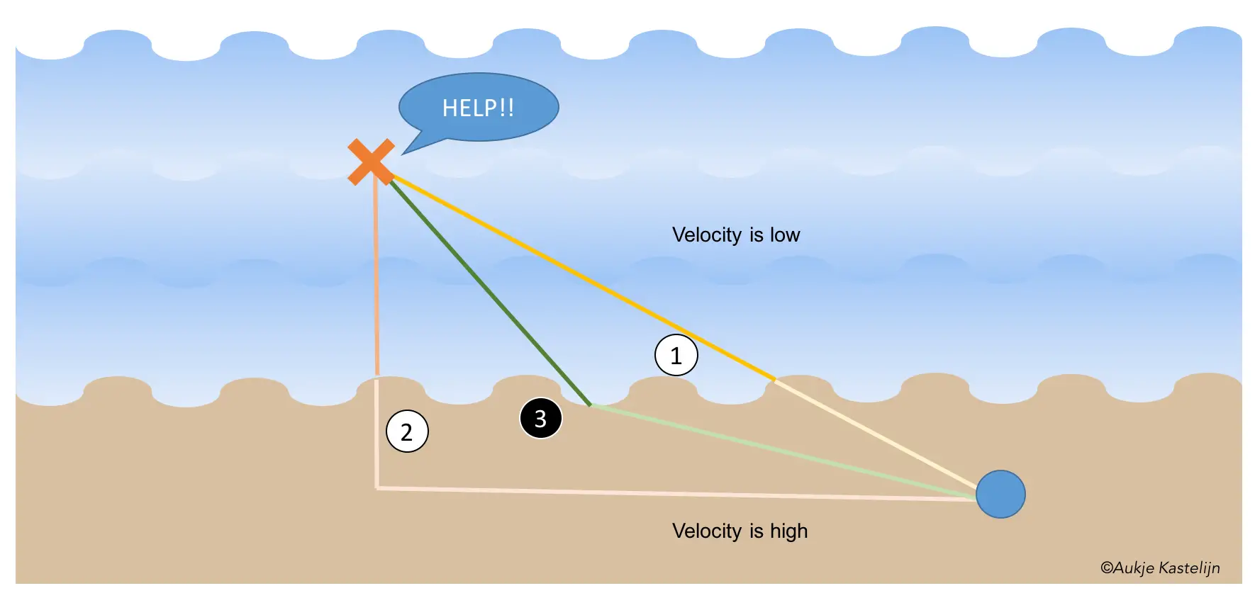
This principle can be translated into a lens, as is shown in the next diagram. Light from a subject, in this case a poppy, will travel via the fastest route to the image in the focal plane, taking into account the lower speed in glass. With an almost spherical piece of glass this will lead to all light coming from one point meeting again in the focus plane. In this case all light paths will require the same amount of time, light going through the centre has a shorter route, but longer path through the glass, while light at the outer parts of the lens will have shorter paths through glass compensating for the longer distance.
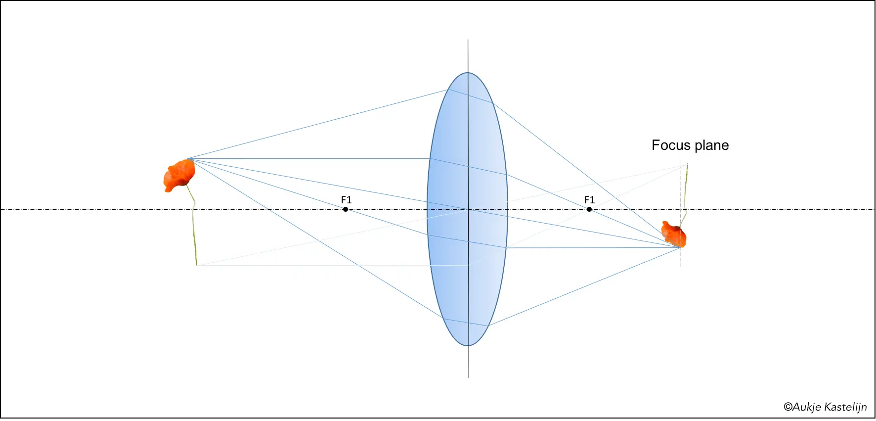
Before going into depth of field and depth of focus I want to give a bit of explanation on how light paths can be constructed. There is a rule of thumb that holds for thin lenses, and I will use it here as it is sufficiently accurate to demonstrate some basic behaviour.
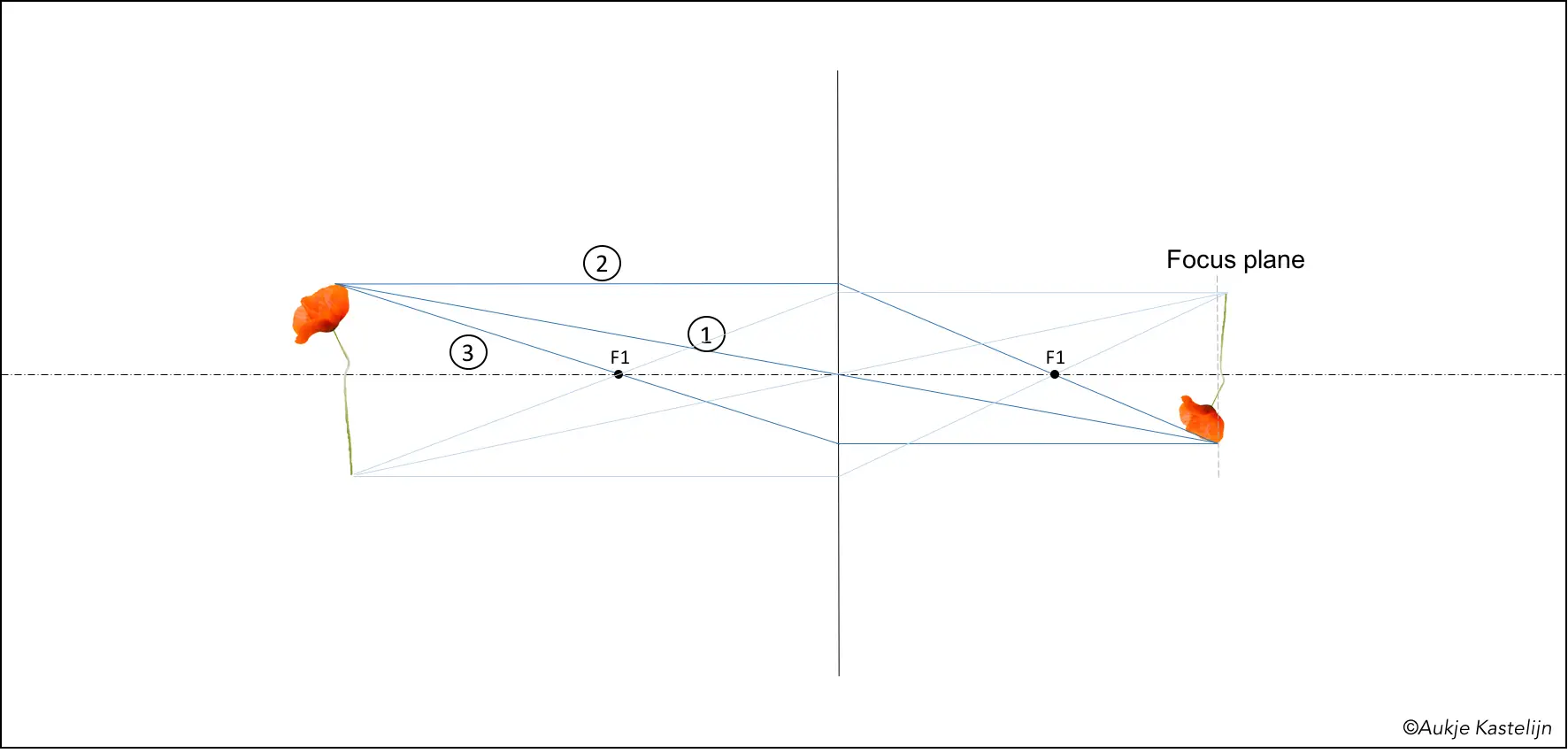
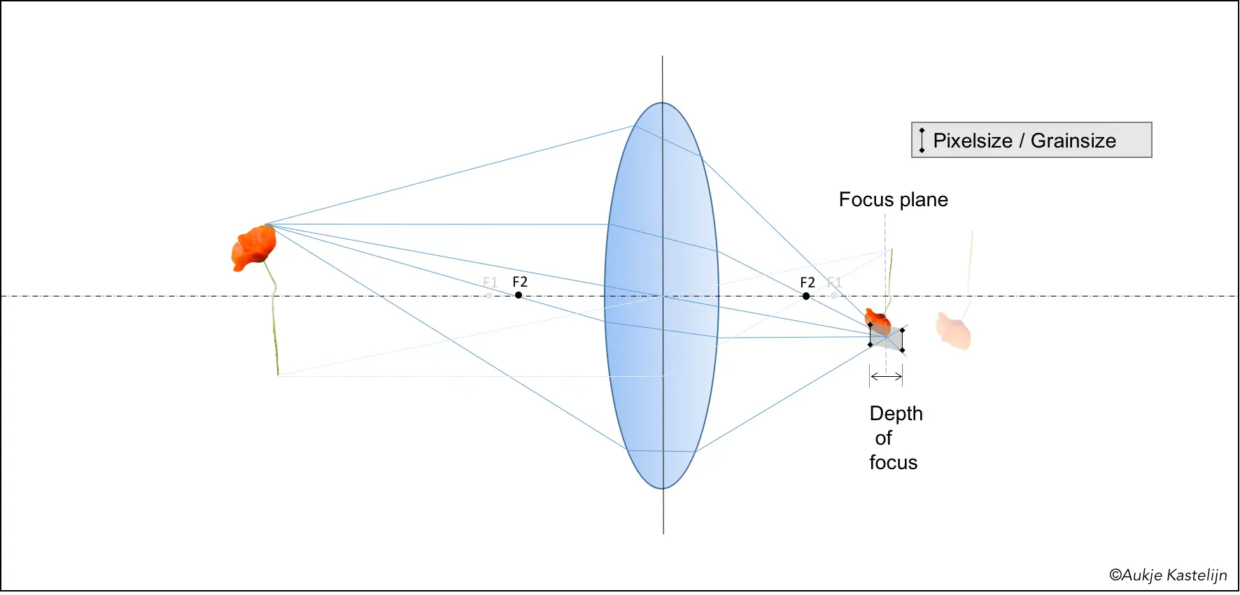
In the diagram below you see the main light rays determining where an image is formed. A light ray coming from the top of the poppy and going through the centre of the lens will move in a straight line (ray 1). Light ray 2, which enters the lens parallel to the optical axis (the dashed line) will leave the lens going through the focal point (F1). And a light ray coming from the same point going through the focal point in front of the lens (ray 3) will leave the lens parallel to the optical axis. All three rays meet in one point, this is where the focal point is, and through this point lies the focal plane. A similar construction can be made for the bottom tip of the stalk. With both points constructed the entire image is determined.
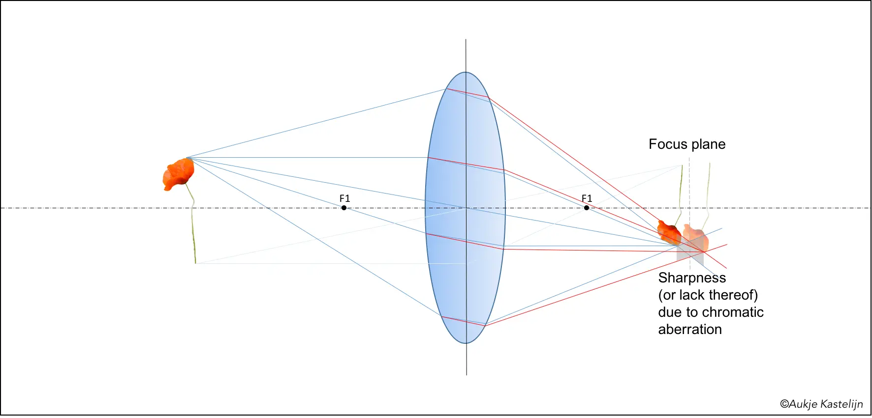
Of course in real life things are not this simple, for example the lens should not be a true sphere, but something similar. This is why there are aspherical lenses, if you calculate the paths with exactly the same traveling time you end up with a shape that is slightly different from a sphere. Besides that, different colours of light have different velocities in glass, resulting in different focal lengths. This phenomenon, called chromatic aberration, is shown in the next diagram, red lights will have a slightly longer focal length than blue. Because of this there is not a real point-image for one point of the subject, but a range where there is some blurred spot. Red and blue are both the extremes, other colours will lie in between. You can see in the image below that the red light is smeared where blue has a point image (closest to the lens), and vice versa further away from the lens. The gray area shows the blurred spot size along the optical axis. The effective focus plane, or the plane where the smaller spot is achieved, is somewhere between the ‘blue’ and ‘red’ focal plane.
Next I would like to demonstrate depth of field and depth of focus, but in view of clarity I will only use the blue rays from here on.
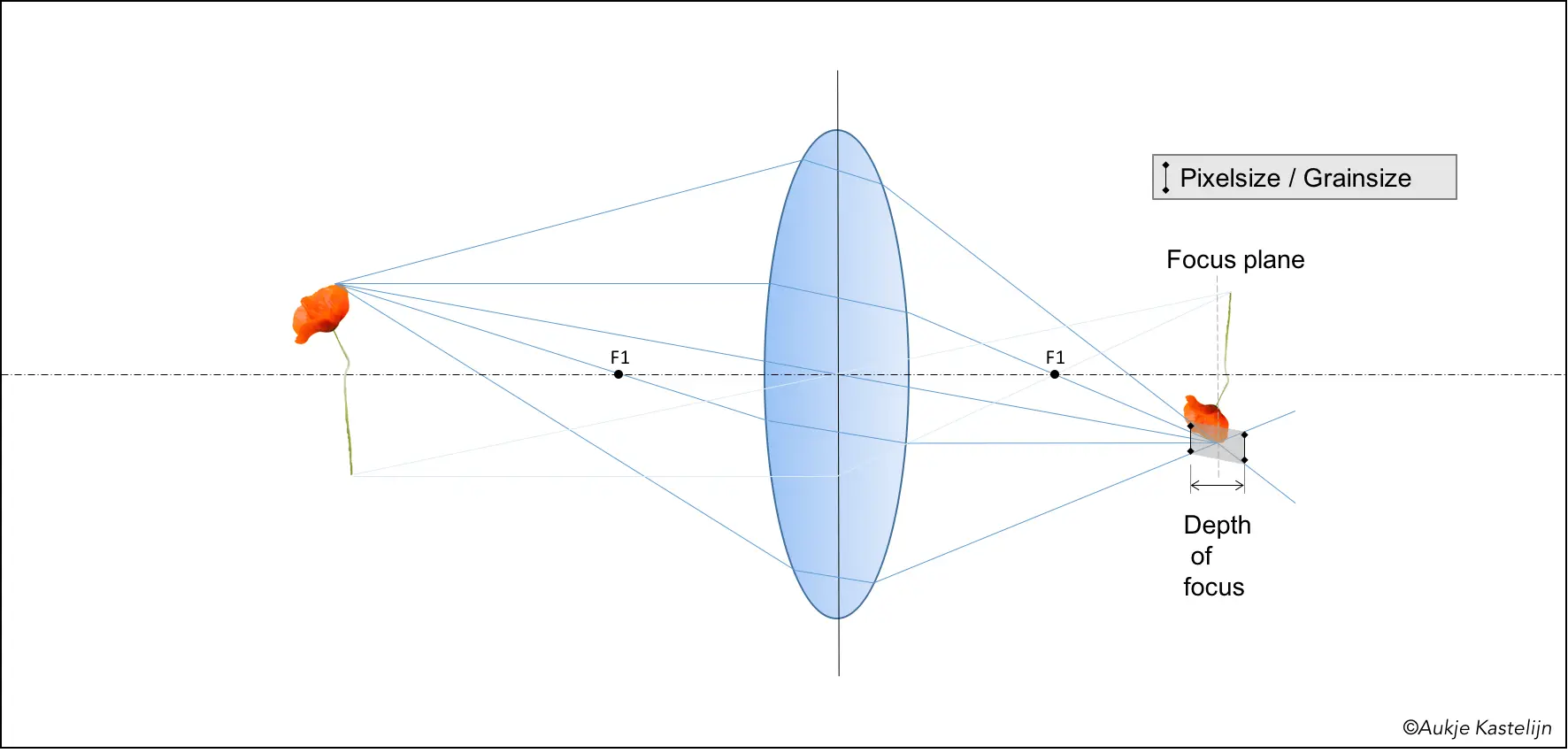
Imagine a perfect lens with aspherical shape and correction mechanisms to correct for chromatic aberration. In theory you would be able to create the perfect sharp image (this is not entirely true, but I have decided that the diffraction limit is out of scope). However, your medium for capturing this image is probably not perfect, being it digital or film. With a digital camera the sharpness is limited by the pixel size, with film it is the grain size. So your image will be perceived as sharp as long as a point is imaged by a spot smaller than this pixel or grain size. This means that there is a range where you can put your image capturing plane in order to get a sharp image. The diagram below demonstrates this, where the black bar indicates the pixel- or grain size. Some distance before and after the focus point of the tip of the poppy the light rays are spread out, but in the gray area this spreading is smaller than the grain size. This distance over which this occurs is called the depth of focus.
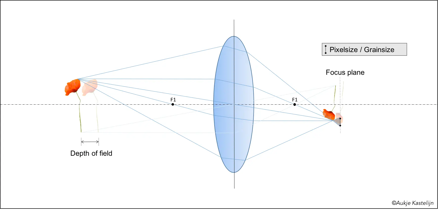
You could also use this freedom to investigate how much room for play there is on the subject side. If you keep your image capturing plane (film) at the same distance as in the diagram below, but put the subject further from the lens, the focus plane will no longer coincide with the film (or digital sensor). However, because we don’t need a perfect point but only a spot smaller than the grain or pixel, this can be allowed to some extent. The next diagram (6, if you are counting) shows how this works. At the distance indicated below the spot size in the focus plane is the same size as the grain. You could move the lens closer to the film or sensor, but you wouldn’t see the difference as you cannot distinguish anything smaller than the grain. This distance over which you can move the subject and still get a sharp image is called the depth of field.
Some parameters that you control can influence the depth of field. But before going into that I thought I’s share an image of a poppy demonstrating small depth of field, just as a fun intermezzo 🙂 .

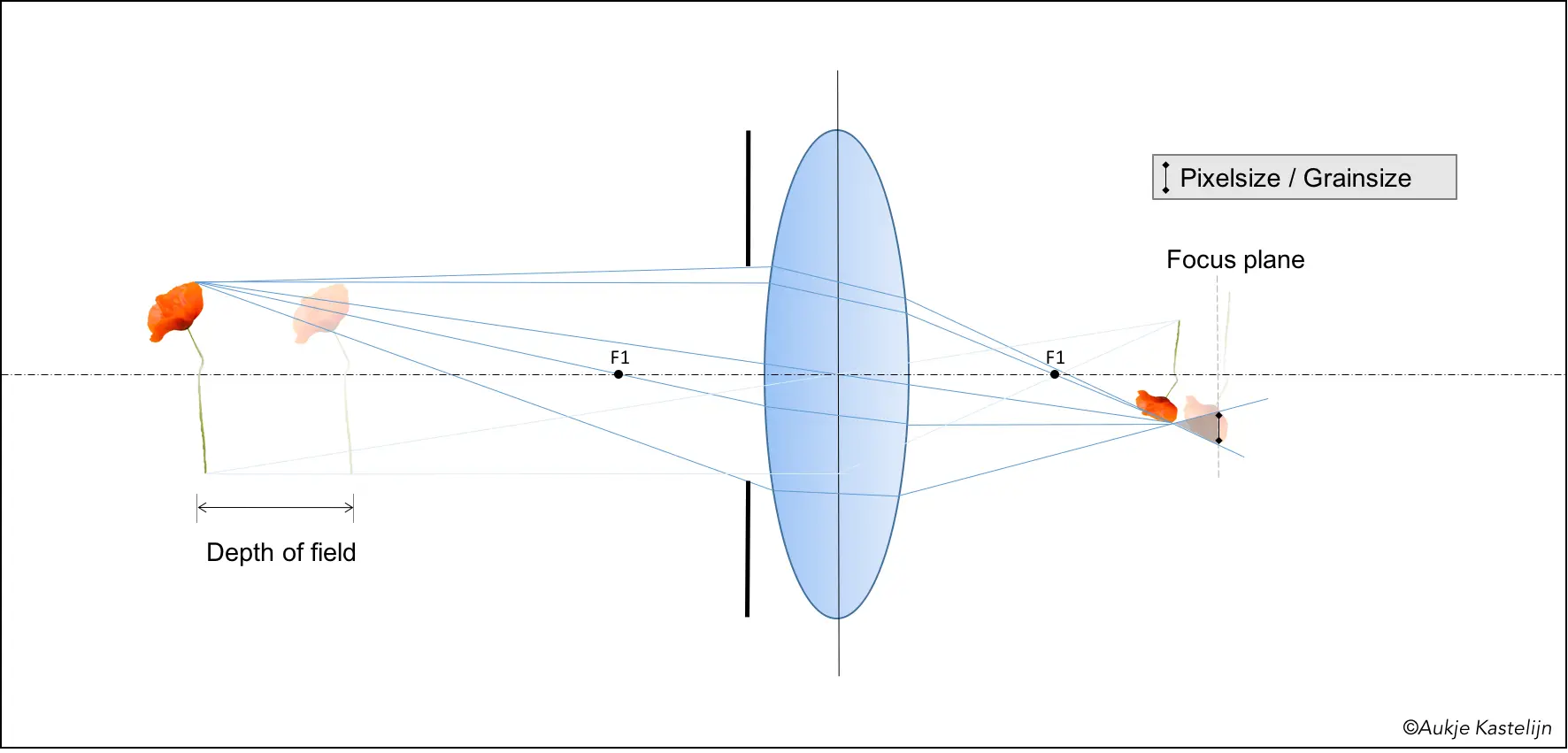
Back to serious stuff: varying the depth of field. One way to do so is by closing the aperture in front of the lens. I hope you can see that by removing the outer rays from the image, the spreading out of the light over the distance is smaller. This leads to more margin with respect to creating spot sizes smaller than the grain or pixel size, and thus leading to a larger depth of field.
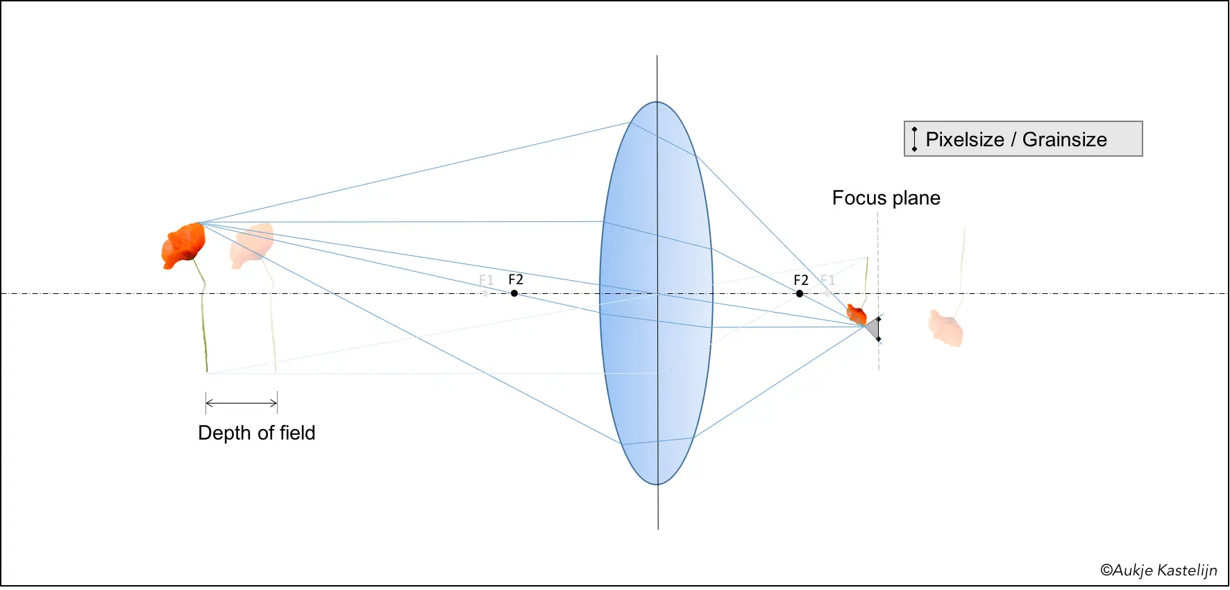
Another parameter influencing the depth of field is the focal distance. Below I show the same diagram with the focal distance F1 as used before, and a new one with a smaller focal distance F2. You can see that the smaller focal distance leads to a smaller image at a plane closer to the lens, if the poppy is located at the same distance from the lens. You can also see that this leads to a smaller depth of focus.
But the change in focal length has the opposite effect on the depth of field, as is demonstrated below. Again showing both the diagrams for F1 and F2 for easy comparison, you see that the lower figure with smaller focal length demonstrates a larger depth of field.

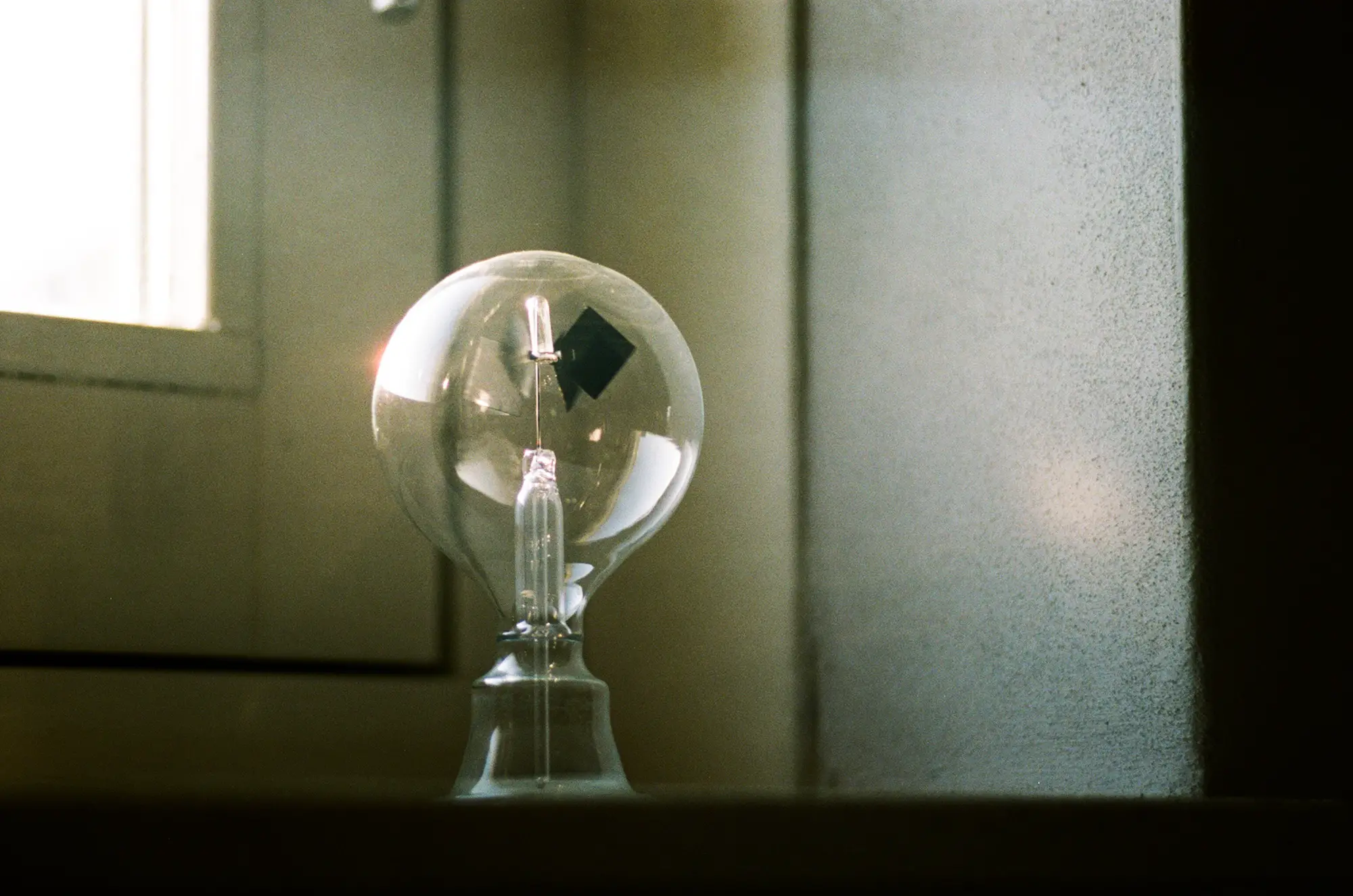
I hope this was as clear to you as it was in my head… Anyway, I enjoyed putting it together, I hope you enjoyed reading it. To finish of I want to share a photo I took of a radiometer, a nice little gadget showing that light has more power than showing us things: it can actually induce motion!
If you are interested I post my photos regularly on my website, and at least one film photo daily (my 366) on my tumblr.
Thanks for reading, and Hamish thanks for having me.
Share this post:


Comments
Eddy on Basic Optics For Photographers In 9 Diagrams – by Aukje
Comment posted: 26/07/2016
Comment posted: 26/07/2016
Michael Rennie on Basic Optics For Photographers In 9 Diagrams – by Aukje
Comment posted: 26/07/2016
Comment posted: 26/07/2016
Mete on Basic Optics For Photographers In 9 Diagrams – by Aukje
Comment posted: 06/08/2019
Comment posted: 06/08/2019
Jesse on Basic Optics For Photographers In 9 Diagrams – by Aukje
Comment posted: 27/12/2019
Comment posted: 27/12/2019
Sroyon on Basic Optics For Photographers In 9 Diagrams – by Aukje
Comment posted: 13/08/2020